Surface Position
The Position tool reports the X, Y, or Z position of a part. You must specify the feature type specified and is one of the following: Average (the mean X, Y, and Z of the data points), Median (median X, Y, and Z of the data points), Centroid (the centroid of the data considered as a volume with respect to the z = 0 plane), Min X, Max X, Min Y, Max Y, Min Z, or Max Z.
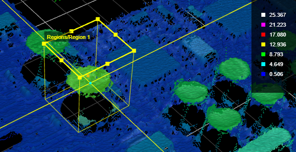
Position X and Y on a PCB component
For information on adding, managing, and removing tools, as well as detailed descriptions of settings common to most tools, see Tool Configuration.
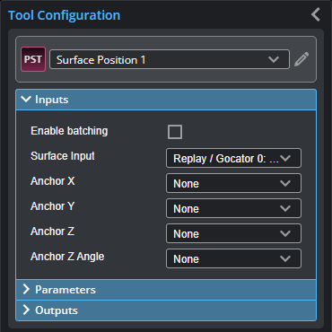
Inputs

|
To use a measurement as an anchor, it must be enabled and properly configured in the tool providing the anchor. For more information on anchoring, see Measurement Anchoring. |
| Name | Description |
|---|---|
| Enable Batching |
For more information on arrays, batching, and aggregating, see Arrays, Batching, and Aggregation. |
|
Surface Input |
The data the tool applies measurements to or processes. This tool can optionally take an array as input. For more information, see Arrays, Batching, and Aggregation. |
|
Anchor X Anchor Y Anchor Z |
The X, Y, or Z measurement of another tool that this tool uses as a positional anchor. Positional anchors are optional. |
| Anchor Z Angle |
The Z Angle measurement of another tool to use as a rotational anchor for this tool. Rotational anchors are optional. |
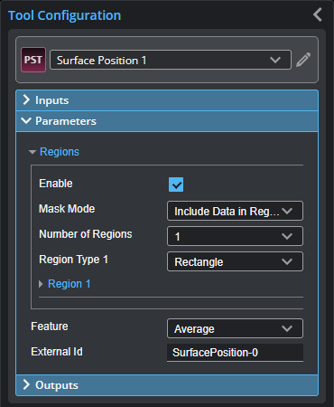
Parameters
The following parameters are in the expandable Parameters section in the tool's configuration.
| Parameter | Description |
|---|---|
|
Regions |
When expanded, displays the region- and mask-related settings. |
|
Enable |
Enables regions and displays the region- and mask-related settings (see below). |
|
Mask Mode Number of Regions Region Type {n} Region {n} |
When you enable regions (see above), the tool displays additional settings related to the region type. For details on the regions supported by this tool and their settings, see Flexible Regions. For general information on regions and the difference between standard and "flexible" regions, see Regions. |
|
Feature |
The feature point types the tool uses. For each, one of the following (for more information, see Feature Points):
When more than one point is at minimum Y or maximum Y (and the feature is set to Min Y or Max Y, respectively), the rightmost point (the one at greater positive X) is selected by the tool. |
|
External ID |
The external ID of the tool that appears in GoHMI Designer. For more information, see GoHMI and GoHMI Designer. |
Outputs
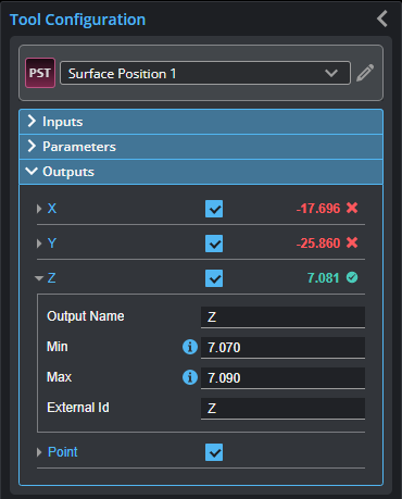
Outputs section with a measurement expanded to show user-configurable decision min/max fields and an external ID
You configure the Min and Max parameters by expanding the measurement in the Outputs section. In order for a measurement to return a Pass decision, the measurement must be between maximum and minimum values; the range is inclusive.
| Measurement | Illustration |
|---|---|
|
X Determines the X position of the selected feature type. |
|
|
Y Determines the Y position of the selected feature type. |
|
|
Z Determines the Z position of the selected feature type. |

| Type | Description |
|---|---|
| Point |
A Point geometric feature representing the returned position. |
|
|
For more information on geometric features, see Geometric Features. |