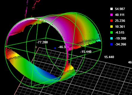
Surface Cylinder
The Surface Cylinder fits a cylinder to scan data and returns measurements and geometric features related to the fitted cylinder. Unlike the Surface Stud tool, the Surface Cylinder tool does not rely on a flat surface perpendicular to the cylindrical object. Examples uses of the tool include fitting to the outside of a cylinder and fitting inside a drilled hole.
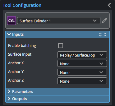
Inputs
You configure the tool's inputs in the expandable Inputs section.
| Name | Description |
|---|---|
| Enable Batching |
When Enable Batching is checked, the tool takes an array as input and processes each element in the array individually. There is no limit to the size of the array, other than the processing limitations of the sensor. For more information on arrays, batching, and aggregating, see Arrays, Batching, and Aggregation. |
|
Surface Input |
The data the tool applies measurements to or processes. |
|
Anchor X Anchor Y Anchor Z |
|
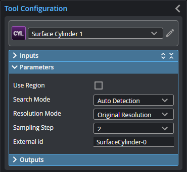
Parameters
You configure the tool's parameters in the expandable Parameters section.
| Parameter | Description |
|---|---|
|
Use Region |
When enabled, displays Region parameters (see below). When disabled, the tool uses all data. |
|
Region |
The region to which the tool's measurements will apply. For more information, see Regions. |
|
Search Mode |
Indicates the expected orientation of the cylindrical target’s axis around the Z axis. One of the following: Auto Detection – The cylindrical target can be in any orientation. Axis in X Direction or Axis in Y Direction – The cylindrical target’s axis is expected to be roughly parallel to the X or the Y axis, respectively. Variation typically must be less than +/- 3 or 4 degrees. Advanced Detection – As with Auto. Detection, the cylindrical target can be in any orientation. This mode can handle some complex scenarios, such as when trying to fit a cylinder to the inside of a hole. Processing time is greater with this search mode. |
|
Resolution Mode |
On G3 sensors, leave this set to the default Original Resolution. Determines whether the tool scales the X or Y resolution so that they are the same (a 1:1 ratio), or leaves the X and Y resolutions as the original. One of the following.
|
|
Sampling Step |
The step in data points in both directions with which the surface is sampled. Choosing a higher sampling step reduces the processing time the tool requires, but reduces fit accuracy. Useful if the surface being processed has a large number of data points. |
|
External ID |
The external ID of the tool that appears in GoHMI Designer. For more information, see GoHMI and GoHMI Designer. |
Outputs
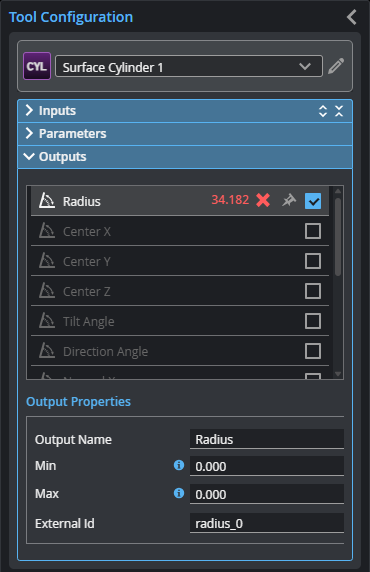
To set what measurement values are considered a Pass, select a measurement in the Outputs list and configure its Min and Max parameters in the Output Properties section. To return a Pass decision, the measurement must be between the maximum and minimum values; the range is inclusive.
| Measurement |
|---|
|
Radius Returns the radius of the fitted cylinder. |
|
Center X Center Y Center Z The X, Y, and Z position of the center of a circle place in the middle of the fitted cylinder |
|
Tilt Angle The angle of the cylinder relative to the XY plane. A cylinder parallel to the XY plane has an angle of 90 degrees. |
|
Direction Angle The angle of the cylinder’s axis around the Z axis. An angle of 0 degrees is parallel to the X axis. |
|
Normal X Normal Y Normal Z These measurements return the X, Y, and Z components of the direction vector of the cylindrical target. |
| Type | Description |
|---|---|
|
Point |
A point representing the center of a circle at the midpoint of the fitted cylinder |
|
Line |
A line representing the axis of the fitted cylinder. |

|
For more information on geometric features, see Geometric Features. |