Connect - Creating a System & Networking
You use the Connect page to see available devices, create a sensor system containing two or more sensors, and also configure network settings. You can also identify devices that are unavailable (either because of a GoPxL version mismatch, or because a sensor is already running through another PC instance of GoPxL). For information on running a sensor through a PC instance of GoPxL, see Running GoPxL on a Windows PC.

|
GoPxL does not currently support mixed-model multi-sensor systems. |
Adding Sensors and Configuring Multi-sensor Systems
|
|
If you are creating a multi-sensor G2 system in a ring layout and intend to perform a high-accuracy alignment (six degree of freedom) using the Surface Align Ring tool (see Ring Layouts (Surface Align Ring Tool)), place all sensors in the Top row, even though some of the sensors will be physically below others. The configuration file created in Surface Align Ring and used in Surface Mesh applies the required transformations to the sensors.
If you are using the built-in stationary polygon alignment (five degree of freedom), create a layout that reflects the physical layout, that is using the top and bottom rows. |
To create a dual- or multi-sensor system
| 1. | In a web browser, connect to the device or PC instance of GoPxL that will control the other devices. |
The default Gocator sensor IP address is 192.168.1.10. If you don't see your sensor in the browser, see GoPxL Discovery Tool.
It may be useful to connect to the leftmost sensor first.
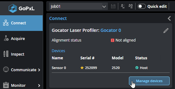
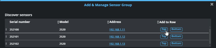
| 2. | In the GoPxL interface, go to the Connect page and click Manage devices. |
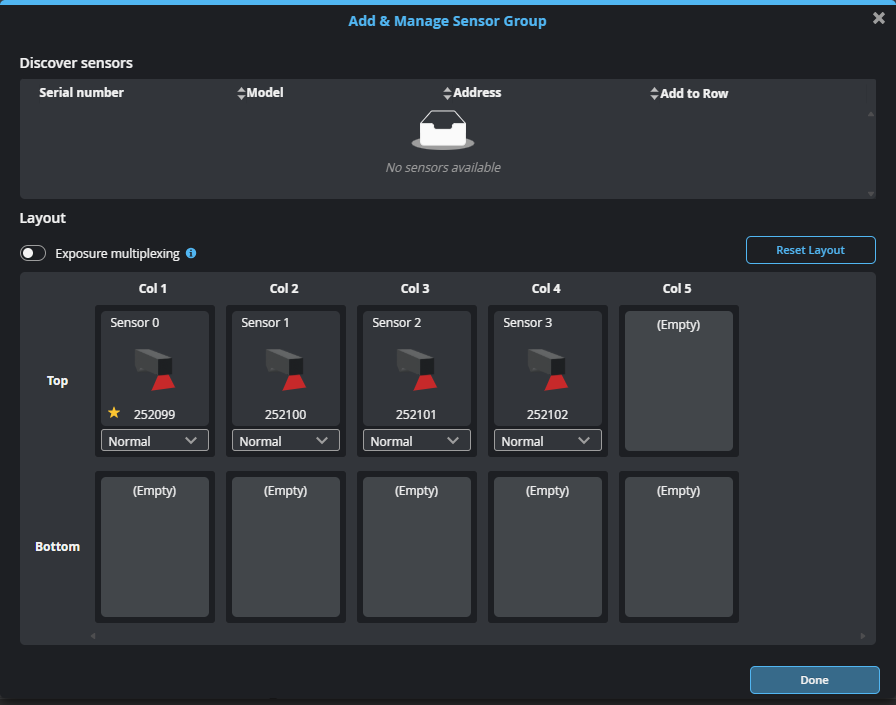
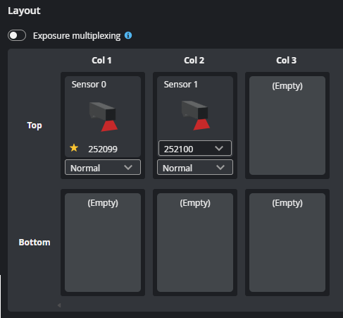
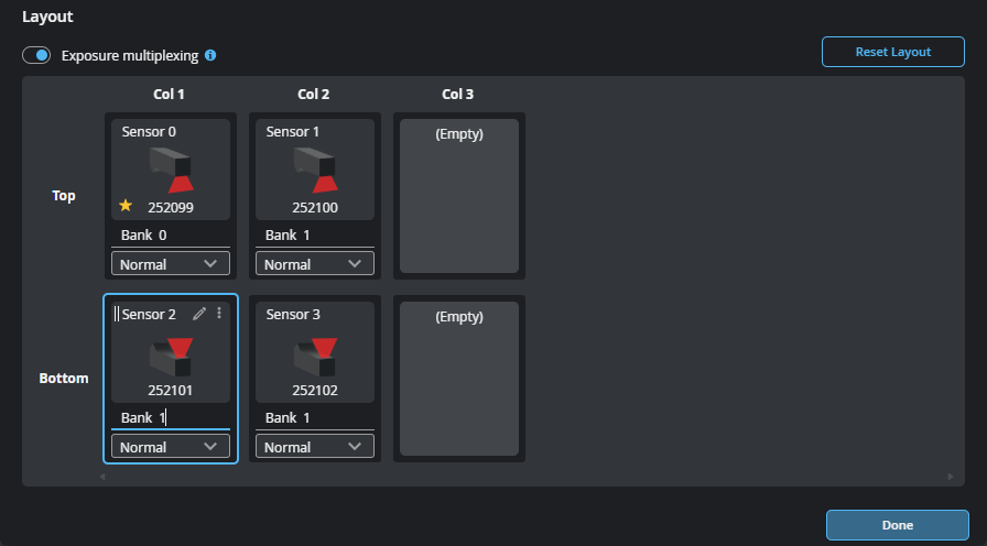
A layout configuration dialog opens, displaying the available sensors, as well as the sensor on which you're using GoPxL in the Layout section. This sensor is indicated by a yellow star ( ).
).
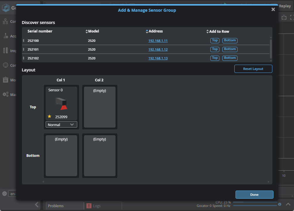
If you don't see sensors you expect to see in the table at the top, close the dialog (Close icon  or Done) and observe which sensors are listed in Visible sensors. These are the sensors that have been detected on the network. If you still don't see the sensors you expect, use the Discovery tool (for more information, see GoPxL Discovery Tool).
| 3. | In the dialog, from the list of available sensors at the top, click the Top or Bottom button next to a sensor to add it to the sensor group in the top or bottom row, respectively. |
The sensor is added to the sensor group.
You can also add the sensor to a specific cell in the grid using drag-and-drop mouse operations, using the grabber icon next to a sensor (![]() ).
).
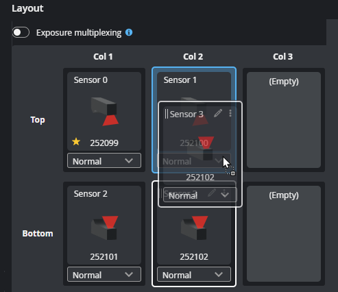
| 4. | (Optional) If you need to reorganize the sensors in the layout, you can hover over a sensor in a grid cell and do one of the following: |
Use drag and drop mouse operations to move a sensor, by clicking on a sensor's grabber and moving it to another cell.
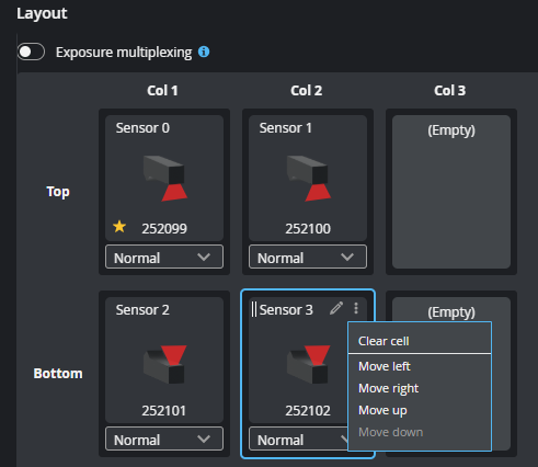
You can also hover over a cell and click the sensor's Show more... icon and choose a "Move" command.
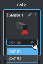
Finally, until all sensors are placed in the layout, you can swap a sensor for another available sensor using a cell's drop-down:
| 5. | (Optional) If necessary, change the orientation of sensors. |
For more information, see Changing Sensor Orientation.
| 6. | (Optional) If necessary, enable exposure multiplexing. |
For more information, see Enabling Exposure Multiplexing.
| 7. | After you have finished configuring your system, click Done and then save your job. |
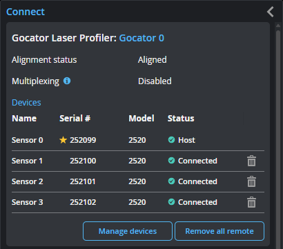
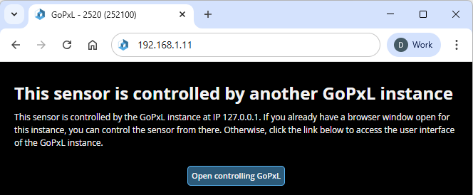
After you have grouped a sensor with another sensor, the web interface of the grouped sensor (also known as a "remote sensor") will show that it's currently being controlled by another GoPxL instance, namely, GoPxL running on the sensor on which you configured the system.
Changing Sensor Orientation
If a sensor's orientation in the layout is such that the sensor's positive Y axis is the same as the motion of the target you need to update the sensor's orientation in GoPxL.
To determine the positive Y axis of your sensor, see the Coordinate System Orientation diagram for your sensor in Sensors.
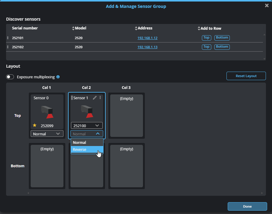
You change a sensor's orientation by changing its orientation to Reverse under a sensor in the layout grid.
Enabling Exposure Multiplexing
To enable and configure exposure multiplexing
| 1. | In the Add & Manage Sensor Group dialog, move the Exposure Multiplexing toggle to the right. |
Bank fields display under each sensor previously added to the sensor group in the Layout area.
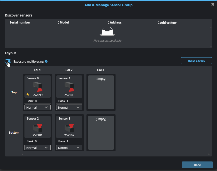
| 2. | Set the values in the Bank fields to assign sensors to the desired banks. |
Removing a Sensor from a System
To remove a sensor from a multi-sensor system, in the Add & Manage Sensor Group dialog, hover the mouse over a cell, click the three dots menu and choose Clear cell. You can also drag a sensor from a layout cell to the sensor list above the layout grid.
![]()
You can also go to the Connect page, and in the row of the sensor you want to remove, click the trashcan icon.
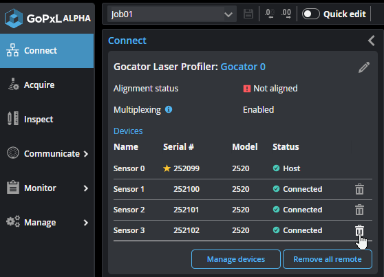
You can remove all grouped (remote) sensors by clicking Remove all remote.
Resetting the Layout
In some situations, you may need to reset the layout. Clicking Reset Layout moves all added sensors to the top row and sets their orientation to Normal.
Network Settings
To configure the network settings:
| 1. | Go to the Connect page. |
| 2. | Specify the type (Manual or DHCP), IP, subnet mask, and gateway settings. |
The sensor can be configured to use DHCP or assigned a static IP address by selecting the appropriate option in the Type drop-down.
| 3. | Click Save Changes.... |
You will be prompted to confirm your selection.
The sensor restarts, using the new IP address. It may take several seconds for the sensor to become available.