Performing the Alignment

|
Currently, GoPxL only supports up to 5 degrees of freedom using the alignment routines on the System > Alignment page. |
For information on coordinate systems, see Coordinate Systems.
Snapshot sensors only support Stationary alignment.
A sensor can be in one of two alignment states: Unaligned and Aligned. An indicator on the Alignment panel displays UNALIGNED or ALIGNED, depending on the sensor's state. A sensor's alignment state determines its coordinate system; for more information on coordinate systems, see Coordinate Systems.
|
|
If you perform a high-accuracy tool-based sensor alignment, the Alignment panel will still display UNALIGNED. This is normal. |
| State | Explanation |
|---|---|
|
Unaligned |
The sensor or sensor system is not aligned. Data points are reported in sensor coordinates. |
|
Aligned |
The sensor is aligned using the alignment procedure (described below) or by manually modifying the values under Sensor Transforms on the System > Alignment page |
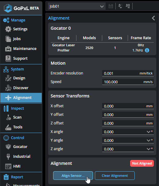
Once you have performed the alignment procedure on the Alignment page, the calculated transformation values are displayed under Transformations in the Sensor Transforms panel on the Alignment page. For more information on transformations, see Transformations.
| 1. | For dual- or multi-sensor systems, make sure you have done the following: |
On the System > Design page, add sensors to the system. For information, see Creating a Sensor System.
Configure the system's layout, if necessary. For more information, see Configuring Power and Creating a Sensor System.
If the profiling lines of the sensors overlap, make sure to check the Exposure Multiplexing option. Otherwise, the profiling line from one sensor will be detected by other sensors and cause the alignment procedure to fail or be inaccurate; for more information, see Creating a Sensor System.
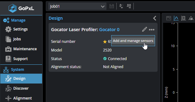
| 2. | Go to the System > Alignment page. |
| 3. | Ensure that all sensors will have a clear view of the alignment target surface. |
| 4. | Perform a preliminary scan of the alignment target to evaluate the quality of the scan data. |
Doing this will help ensure that the alignment process succeeds. In the next step, adjust the settings based on the scan data of the alignment target.
| 5. | If necessary, on the Inspect > Scan page, adjust the sensor settings to get the best data possible from the scans of the alignment target. |
Some examples of the settings you may need to adjust are:
- Exposure duration (to make sure the target is clearly represented in the scan data). Typically, only a single exposure is needed. For more information, see Single Exposure.
- Active area. For more information, see Active Area.
- Spacing:
Because the alignment procedure automatically uses Time triggering, regardless of the settings in the Trigger panel, you can leave these settings as is and configure them later. For information on triggering, see Triggers.
| 6. | Perform the steps in Performing Stationary Alignment. |
Performing Stationary Alignment
To perform stationary alignment
| 1. | Make sure that the alignment surface (whether it's the surface of a conveyor or of an alignment target) is within the sensor's measurement range. |
To determine this, in the sensor's web interface, click Start and observe whether the Range LED on the sensor is illuminated. If you have set the trigger source to Encoder under Inspect > Scan > Trigger, temporarily set it to Time for this. Be sure to stop the sensor after confirming the target is in range by clicking the Stop button.
Alternatively, you can determine the correct distance to the scan surface by consulting the sensor's measurement range specifications (see Sensors), and measuring the physical distance between the scan surface and the sensor.
| 2. | Go to the System > Alignment page. |
| 3. | (Optional) If a previous alignment is present, click the Clear Alignment button. |
| 4. | If you are using an alignment target, place it below the sensor or sensors. |
| 5. | On the System > Alignment page, click Align Sensors. |
The Alignment dialog appears.
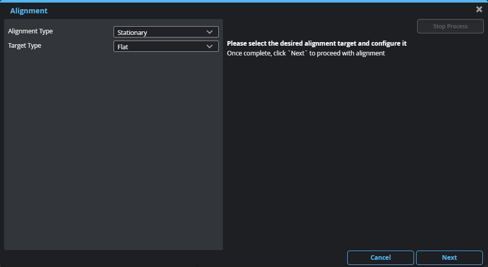
| 6. | Set Alignment type to Stationary. |
| 7. | Choose an alignment type in Alignment type. |
- Flat Surface:
- Stationary Plate: Use this to align to an alignment plate you have manufactured. For more information, see Stationary Plate.
| 8. | Click the Next button. |
If the alignment fails, check the settings described in To prepare for alignment and repeat the steps described here.
| 9. | Inspect alignment results. |
Check the alignment results under Sensor Transforms.
For information on how alignment affects the coordinate system used by sensors, see Coordinate Systems.
Stationary Flat Surface
No additional settings are required for this alignment method. Note however that this type of alignment expects to receive flat scan data. Therefore, if the surface is curved, the alignment will be inaccurate. The surface should also be clear of debris and damage.
Stationary Plate
You can align a G3 sensor using an alignment plate with one or two holes. The table below describes the transformations resulting from aligning using each kind of target.
Target Specifications
Make sure of the following when manufacturing an alignment plate:

- Holes must be as sharp as possible: avoid bevels.
- The size of the holes should be more than 10 times the XY resolution of the sensor; for the XY resolution of your sensor, see specifications of the sensor in Sensors.
- Sensors must capture as little data from the inside of a hole as possible. Either countersink holes from the opposite side of the plate, or paint the insides of the holes with a flat black paint. Otherwise, although the alignment should succeed, it will not be as accurate: it may result in unwanted offsets or angles in the transformations.
- The recommended flatness of alignment targets for accurate Y angle is roughly the Z resolution rating of the sensor. If the bar target is curved, it will introduce an apparent Y angle in the sensor alignment. For sensor Z resolution, see the specifications for your sensor in Sensors.
- It is not necessary to machine the plate height to a high tolerance. Height can instead be controlled during measuring rather than at manufacture. Only flatness is important. If the zero level is not critical for the measurement, then standard machining tolerances can be used. Alternatively you can machine to a low tolerance and measure the value to a high precision to save cost.
- Plates should be painted with flat light grey or white paint to improve data capture (by reducing the possibility of reflections and improving profile data of the bar surface).
Configuring GoPxL for Plate Alignment
Configure the characteristics of the target; for more information on these settings, see below.
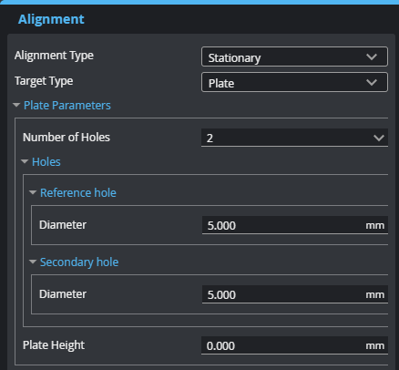
- Number of Holes is the number of holes in the alignment plate. For information on the transformations resulting from different types of plates, see Transformations resulting from plates.
- Diameter: Sets the diameters of the holes. If you are using a plate with two holes, they must be of different sizes.
- Plate Height: The alignment procedure determines the average Z height of the alignment target's top surface and uses the value specified in Height to offset the coordinate system from that average Z height; in effect, the bottom of the alignment target becomes the Z origin (the zero reference level).
