Digital Output
GoPxL can send digital signals over a sensor's digital outputs based on measurement decisions, software commands, and other events. These signals can then be used to control a PLC or other external device, such as indicator lights or air ejectors. The following trigger events are available:
- Measurements
- Software (that is, a command sent from GoPxL SDK applications)
- Alignment state
- Exposure begin or end
- Part detection
- System state (that is, when the system is ready to accept digital input triggers)
GoPxL provides two digital output channels. For information on wiring digital outputs to external devices, see the following:
Counts of low and high digital signals, as well as digital output drops, are available on the Health page, in the expandable Sensor {n} sections. For more information, see Health.

|
Digital outputs cannot be used when taking scans using the Snapshot button, which takes a single scan and is typically used to test measurement tool settings. Digital outputs can only be used when a sensor is running, taking a continuous series of scans. |
| Element | Description | |
|---|---|---|
|
1 |
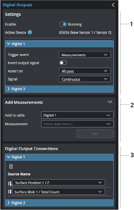
Settings |
Enable lets you enable digital output. Active Device shows which sensor's digital output port GoPxL will send digital signals. Each expandable "Digital {n}" section lets you choose the type of trigger event and configure settings related to the signal. When you set Trigger event to Measurements, you use the Add Measurements and Digital Output Connections sections to add and manage the measurements that GoPxL sends as digital outputs. Otherwise, a digital signal is sent when the selected trigger event occurs. For information on the trigger settings, see Digital Output Settings. |
|
2 |
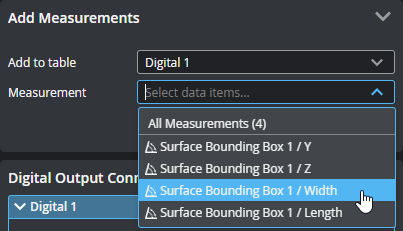
Add Measurements |
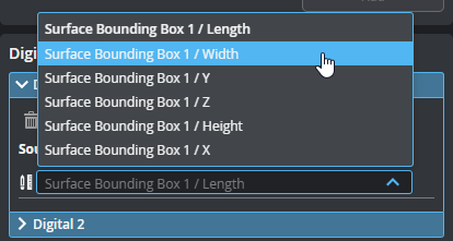
Lets you choose a measurement and which digital output the signal is sent over. This section is only displayed if at least one digital output's trigger is set to Measurements. To set a measurement for digital output, choose the output in Add to table, choose the measurement in Measurement, and click Add. You can also add all measurements at once by selecting "All Measurements".
After adding a measurement, it appears in the Digital Output Connections section of the digital output you chose. |
| 3 | Digital Output Connections |
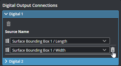
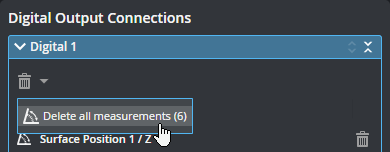
Lets you view, delete, and change the measurements that trigger a digital output signal. This section is only displayed if at least one digital output's trigger is set to Measurements. To delete a measurement, click the trashcan icon next to it.
You can also use shortcut commands to delete all of the connections.
To change a measurement, click an output's drop-down and choose a different measurement.
|
| Parameter | Description |
|---|---|
| Trigger event |
GoPxL can send a digital output signal when one of several trigger events occurs. Depending on the event you choose, other parameters are displayed that you may need to configure. For more information, see the other parameter descriptions below.
Measurements GoPxL sends a digital signal based on the decisions, for each frame, returned by the measurements added to the digital output. Set Signal to choose between a pulsed or continuous signal. Optionally, set a pulsed signal to be scheduled with Scheduled. You must set Assert on to configure what types of measurement decisions result in a digital signal. Software When GoPxL receives a software command from a GoPxL SDK application, it sends a digital signal over the configured digital output. Use Signal to choose between a pulsed or continuous signal. Optionally, set a pulsed signal to be scheduled with Scheduled. For pulsed or scheduled pulse, the sensor must be scanning before sending the command. For continuous signal, the sensor does not have to be scanning Alignment When a sensor is in an aligned state, GoPxL sends a continuous digital signal. Only alignment performed using the Alignment routine on the Acquire page results in a trigger event (for more information, see Aligning Sensors with up to 5 Degrees of Freedom): alignment performed using the Surface Align Wide or Surface Align Ring tools does not. Whether the sensor is running does not affect the output.
Exposure begin GoPxL sends a pulsed digital signal with the provided pulse width when exposure begins.
Exposure end GoPxL sends a pulsed digital signal with the provided pulse width when exposure ends.
Part detection You can use GoPxL's part detection capabilities as a digital output trigger. This lets you use the sensor as a photo-eye, for example, eliminating the cost of installing a separate photo-eye. In this mode, GoPxL sends a continuous digital signal if the part detection logic is currently scanning at least one part, that is, GoPxL determines it is currently "in" at least one part. When GoPxL is no longer scanning a part, the signal goes low.
System state GoPxL sends a continuous digital signal when the sensor is ready to receive digital input to start triggering for scanning when the following modes are set on the Acquire page:
For more information on triggers, see Triggers. For more information on surface generation, see Surface Generation. |
| Invert output signal |
Inverts the output signal. Normally, GoPxL will send a high digital signal when an event occurs. Toggling this setting causes GoPxL to send a low signal when the event occurs. |
| Assert on |
When Trigger event is set to Measurement, use this setting to determine which type of decision in the measurements added to the output in Digital output connections cause GoPxL to send a digital signal. GoPxL checks decisions for each frame. One of the following:
All pass: If all added measurements return a pass decision, GoPxL sends a digital signal.
Any fail or invalid: If any added measurement returns a fail decision or Invalid, GoPxL sends a digital signal.
Always: GoPxL sends a digital signal, for each frame, after the tools producing the selected decisions have finished processing, regardless of the result (pass, fail, or invalid). The output activates only once for each frame even if multiple decision sources are selected. LMI recommends using pulsed digital signals with this mode, as otherwise the signal will remain high indefinitely. |
| Signal |
Measurement and Software trigger events let you choose the signal type (pulsed or continuous).
Pulsed GoPxL sends a pulsed signal over the digital output, using the value you set in Pulse width.
Continuous GoPxL sends a continuous signal over the digital output. When the trigger event is Measurement and Assert on is set to always, LMI recommends using pulsed digital signals instead of continuous. |
| Pulse width | The pulse width used when the signal type is pulsed. Note that Measurement and Software trigger events let you choose between pulsed and continuous, whereas the exposure types are always pulsed. |
| Scheduled |
When this setting is enabled, you can set a delay using Delay and Delay Domain. Only Measure and Software trigger events let you schedule output. |
|
Delay Domain |
The delay and domain GoPxL uses when Scheduled is enabled. The delay domain is either time-based or based on encoder distance. |
| Delay | The unit depends on whether the domain is time (microseconds) or encoder (millimeters). |